Global web icon
wikipedia.org
https://en.wikipedia.org/wiki/NAND_gate
NAND gate - Wikipedia
In digital electronics, a NAND (NOT AND) gate is a logic gate which produces an output which is false only if all its inputs are true; thus its output is complement to that of an AND gate.
Global web icon
electrical4u.com
https://www.electrical4u.com/nand-gate/
NAND Gate: What is it? (Working Principle & Circuit Diagram)
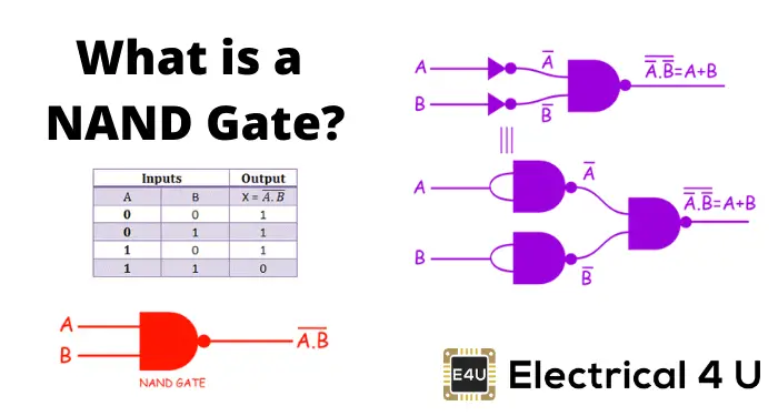
What is a NAND Gate? A NAND gate (“not AND gate”) is a logic gate that produces a low output (0) only if all its inputs are true, and high output (1) otherwise. Hence the NAND gate is the inverse of an AND gate, and its circuit is produced by connecting an AND gate to a NOT gate.
Global web icon
geeksforgeeks.org
https://www.geeksforgeeks.org/digital-logic/what-i…
NAND Gate - GeeksforGeeks
In this transistors acts as a small switches in a circuit, turning on or off based on the signal received from the input. In NAND gate, transistors is used to make sure that the output is low (0) only when all of its inputs are high (1).
Global web icon
electronics-tutorials.ws
https://www.electronics-tutorials.ws/logic/logic_5…
Logic NAND Gate Tutorial with Logic Circuit & Truth Table
Digital Electronics Tutorial about the Logic NAND Gate and the Logic NAND Gate Truth Table used in digital TTL and CMOS logic gate circuits
Global web icon
build-electronic-circuits.com
https://www.build-electronic-circuits.com/nand-gat…
NAND Gate - Logic Gates Tutorial - Build Electronic Circuits
Learn how the basic electronic components work so that circuit diagrams will start making sense to you. This is the basics of the NAND gate. Learn how it works, its truth table, boolean expression, and much more with this logic gate tutorial.
Global web icon
electronicshub.org
https://www.electronicshub.org/universal-gates-nan…
NAND Gate: The Building Block of Digital Circuits (Explained)
The NAND gate: tiny but mighty! Explore why it's called a universal gate and how it's used to build ALL logic circuits. Demystify digital logic with this beginner's guide!
Global web icon
hackatronic.com
https://hackatronic.com/universal-nand-gate-truth-…
NAND Gate Truth Table, Logic Circuit & IC 7400 Pin Diagram
Explore Universal NAND Gate from its truth table to its IC pin diagram, delve into transistor-based logic circuit construction and working, and discuss the advantages, disadvantages, and various applications of the NAND gate.
Global web icon
dyethin.com
https://www.dyethin.com/blog/industry/understandin…
Understanding NAND Gate: The Universal Logic Gate in Digital Circuits ...
Learn everything about NAND gates, the universal building block of digital circuits. Discover their truth table, applications in computing, and why they are essential for modern electronics and AI processors.
Global web icon
siliconvlsi.com
https://siliconvlsi.com/nand-gate-symbol-truth-tab…
NAND Gate- Symbol, Truth Table, Circuit Diagram - Siliconvlsi
What is NAND Gate? When you use a NAND gate (short for “NOT-AND” gate), you’re working with a logic gate that gives an output signal only when all its input signals are NOT true. Essentially, it’s an AND gate followed by a NOT gate.
Global web icon
electricalvolt.com
https://www.electricalvolt.com/logic-nand-gate-sym…
Logic NAND Gate- Symbol, Truth Table, Circuit Diagram, Working
In this article, we will discuss the logic NAND gate, its definition, truth table, Boolean expression, electrical equivalent circuit, and more. So, let’s get started with the basic definition of logic NAND gate.